|
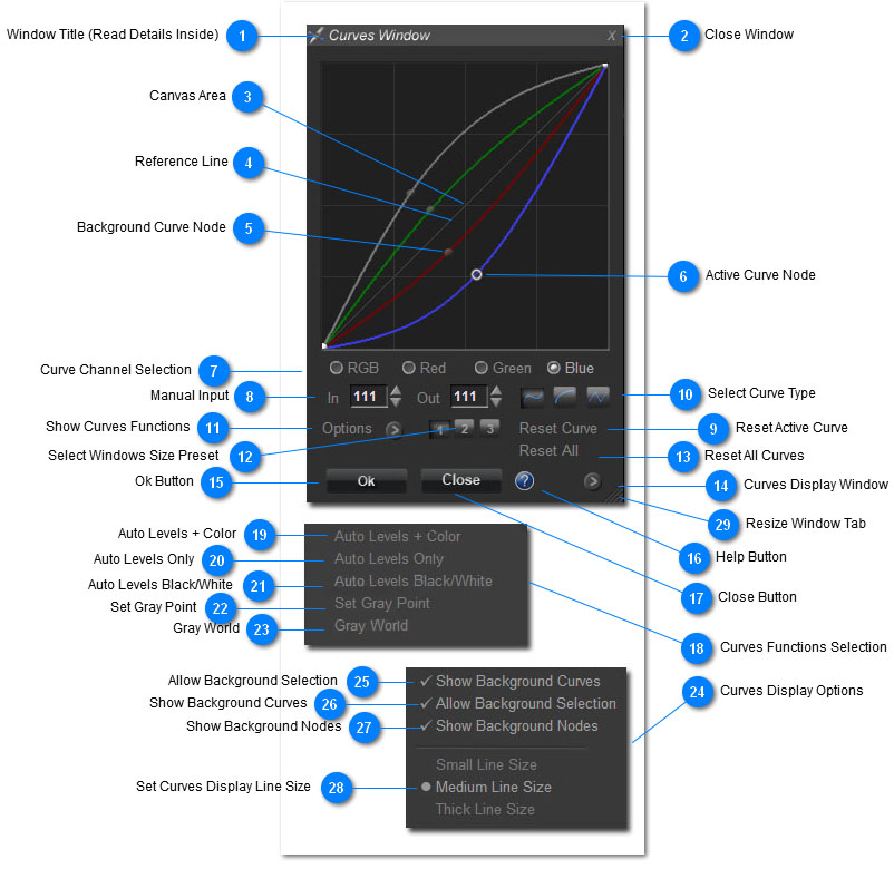
Quick Reference (Curves Window in the Quick Edit and Pro-Quick Edit Modes)
Hover the mouse over the circular tabs for a description of each function
<TODO> Insert description text here... And don't forget to add keyword for this topic
 Window Title (Read Details Inside)
The Curves Window in the Quick Edit Mode and Pro Quick Edit Mode, in terms of general operation, acts the same as it does in the Power Curves and elsewhere in Sagelight.
After that, the behavior changes, as the Curves in the Quick Edit & Pro Quick Edit Modes are fine-tuned to those modes, as opposed to general curves. See the general section on the Curves in the Quick Edit and Pro Quick Edit Modes
Mouse and Keyboard Controls
Fine Tuning the Result:
Up & Down Arrow. When a node is highlighted, you can use the Up and Down Arrows on the keyboard to fine tune the result.
Scroll Wheel. Use the Mouse Scroll Wheel to also fine-tune the result.
Control Key. Use the Control Key while using the Up/Down Arrows or Mouse Wheel to refine the result even further.
Display Image Value in the Curves Box
Move the mouse on the screen to show the relative position in the active curve. For example, if the active curve channel is Red, the corresponding red value will be highlighted on the curve. As you move the mouse around, the value will change. This is the equivalent to the input value for whatever pixel the mouse is currently over. This is also true of the HSL and C*I*E LAB mode in the Pro Quick Edit Mode.
Selecting a Point from the Image
Right-Click on the mouse to select the point that is being display in the curve. As you move the mouse over the image, the corresponding input value will be displayed. Right-click on the screen to make this point permanent. Be careful about pressing the left-mouse button, as this may activate a masking control.
Starting a New Node/Anchor Curve Point
Click anywhere on a Curve to start a new anchor node. You can immediately start moving the point around. Clicking in an empty space in the Curves Box will also start a point, in the input area for that point in the curve channel selected -- the output value will be the empty point you clicked, which will move the curve point to the mouse cursor.
Selecting an Existing Point
Click near a highlighted node to select that node. The node will highlight when you are near it to indicate that it may be selected.
Selecting a Background Curve
You can select a background curve by simple clicking on it. As you move the mouse around, the curve will semi-highlight to let you know that if you click on it, it will be activated. If you are over a current anchor node in the background curve, this point will be selected. If not, then a new point will not be created.
|
 Close Window
Press this button to close the window. This is the same as pressing the Cancel Button. The existing curves will be canceled, and the box will close. No changes will be made to the image.
|
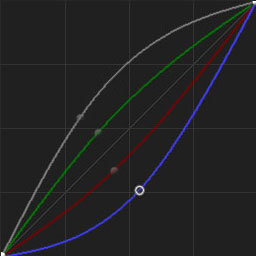
 Canvas Area
This is the general canvas/curves box where you may create, select, and manipulate the curves. This box is resizable. See the other controls descriptions.
|
 Reference Line
This thin, semi-white line is the reference line, which indicates a 1:1 input/output. For example, input value 100 and output value 100 lie in this line, which means no change will be made to your image (which is why the line is at a 45-degree angle). This is the natural reset/initialized setting for all curves in the Quick Edit Mode and Pro Quick Edit Mode. In other modes, this may vary.
|
 Background Curve Node
Solid, grayish nodes indicate anchor/node points in a non-selected curves. This is displayed for reference.
|
 Active Curve Node
This shows an active node that is also highlighted. When an active node is highlight, you may click on the mouse to move and change the point.
Also, the keyboard and mouse wheel change this point for fine-tuning.
|
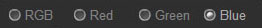
 Curve Channel Selection
This selects the current channel. In most cases, you do not need to use these checkboxes, as you can select the curve for each channel directly, simply by clicking on it.
However, sometimes curves overlap each other and it is hard to select the background curve. Use these checkboxes to select a curve that is obscured by another curve.
|
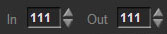
 Manual Input
As you move around the mouse with a selected point, this value will change to show the input and output value. You can change these values manually.
You can also place the mouse on the up/down arrows to fine-tune both the input and output values.
The Up/Down Arrows and Mousewheel (with and without the Control-Key) will also fine-tune the output value (but not the input value).
|
 Reset Active Curve
This resets the active/foreground curve. The other curves are not changed.
|
 Select Curve Type
This selects the curve type.
1. Standard Curves. The leftmost button is the default, and generates curves that are basically industry-standard, using a steep angle, which allows curve points to be close together without overlapping each other.
2. Symmetrical Curves. This sets a loose curve setting that allows curves to operate in a more symmetrical manner. This can be useful for avoiding shadows and highlights, and generally making symmetrical curves (i.e. low and high values). These can be very useful under some circumstances when the Standard Curves are harder to deal with.
3. Segment Lines. This sets a series of segment lines, from node-to-node. These can be very useful in identfying hotspots and other curve points you want to refine; you can then switch to standard curves to make sure the node points transition smoothly.
|
 Show Curves Functions
This will open the Curves Function Window.
The Quick Edit Mode and Pro Quick Edit Mode curves have a number of functions to allow you to remove color casts and balance your image. These are the same routines used elsewhere in Sagelight, but you have much more control because you can directly change the result.
See the notes below.
|
 Select Windows Size Preset
You can change the size of the window manually by dragging the lower-right corner of the window out.
These buttons provide easy Small, Medium, and Large sizes for the window. More than that, these sizes are design to not alias, where other sizes may show edges on the curve lines.
Button 1. This sets a 256x256 window size
Button 2. This sets a 384x384 window size.
Button 3. This sets a 512x512 window size
|
 Reset All Curves
This button will reset all curves and any other settings to their initial state, and will leave your image untouched (from the curves)
|
 Curves Display Window
Opens the Curve Display Window where you can set the style and behavior of the curves display and selection. See the notes below.
|
 Ok Button
Quick Edit Mode Only: Press this button to Apply your changes. In the Quick Edit Mode, this will apply ALL Quick Edit Mode controls to your image and acts the same as the Apply Button.
This button does not exist in the Pro Quick Edit Mode
|
 Help Button
Press this button for more help on the Curves Window.
.
|
 Close Button
This closes the Curves Window, resetting all curves back to 0.
|
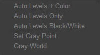
 Curves Functions Selection
In this selection box, you can perform a number of functions. These are detailed below.
In general, these functions are the same as either the "Remove Color Cast" or "Auto Balance" function in Sagelight. However, you have much more control since you can change the result directly.
If you try some of these functions against the equivalent Sagelight functions, you will see the exact same result most of the time, only with the curves set to the result so they can be changed.
Important Note: The Auto Balance in Sagelight will protect your image by drawing back on the auto balance when it sees it is about to overflow a highlight. This does not occur with these functions. Since you have control over the result, this action is not needed. You can compensate for it with the RGB curve.
|
 Auto Levels + Color
This performs an Auto Levels and Auto Color, and is the same as the algorithm in the Auto Balance controls.
Note, however, that it does not protect your image as the Auto Balance does -- your highlights may become bright. Use the RGB curve to control this result.
|
 Auto Levels Only
This performs an Auto level on all channels with a clipping level of .1 percent. Use the RGB curve to adjust the brightness and shadow level of the result. You can use the histogram to see what is occuring in the image.
|
 Auto Levels Black/White
This performs an RGB levels, adjusting the brightness only. Use the RGB curve to adjust the brightness of the highlights in the result.
|
 Set Gray Point
Use this to click on the image to set the gray point for the image. This is the same as "Remove Color Cast", except that you have more control (since you can manipulate the curves), and it does not perform an auto-levels by default.
|
 Gray World
This is unique to the Quick Edit Mode and Pro Quick Edit Mode curves. This performs a "Gray World" algorithm, which can help balance your image -- it's always worth a try, as sometimes it works very well, and even when it doesn't, it puts you in a great place to change the resulting curves.
The algorithm essentially calculate the average of your image and sets the midpoint values to reflect the difference.
|
 Curves Display Options
This allows you to change how the curves are displayed and selected. See the notes below.
|
 Allow Background Selection
By default, you can select background curves just by clicking on them. Uncheck this to disable this feature. When unchecked, background curves must be selected through the channel selection checkboxes.
|
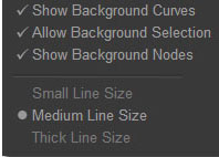
 Show Background Curves
This will show all of the background curve channels. For instance, if you are using the Red Channel Curve, the RGB, Green, and Blue channels will display in the background. Unchecking this box will display only the current curve.
|
 Show Background Nodes
By default, the anchor nodes of the background curves show on the screen. Unchecking this box will not show the nodes on the background curves.
|
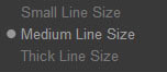
 Set Curves Display Line Size
By default, the size of the curves lines as drawn is a medium thickness. You can change this to a small, thin line, which can give you more accuracy in creating your curves, or change it to a thicker line which can give your curves more visibility.
|
 Resize Window Tab
Grab this and move it to resize the Window to any size you wish. You can also use the '1', '2' and '3' buttons for preset sizes.
This can be useful when you wish to work at a higher resolution with a curve -- you can resize the box temporarily and then put it back, or resize it and then use one of the preset size buttons ('1','2', or '3').
|
|
|